UML Component Diagram
Note
UML component diagrams are a static view of a system depicting it's design at a specific time of it's development and/or evolution.
They focus on high level structure like whole components and their interactions/relationships more than details like attributes, implementations or methods, so these diagrams are useful early in the design process.
Components are the independent, encapsulated units within a system and they provide an interface for the interactions between them.
The basis of component diagrams are components and their relationships, each component has a very specific relationship with other components through interfaces:
- Provided interface
- Required interface
And these interfaces form an assembly relationship where a components required interface matches another's provided interface.
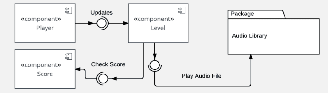
When building a Component diagram you need to follow some steps:
- Need to identify the main objects used in the system as components.
- Identify all the relevant libraries you would need for the system as components.
- Come up with the relationships between these components.
